A Simple Electric Circuit Has 20v Battery And Resistor Of 100 Ohm What Is The Current

101 200 Transistor Circuits Electronic Schematics Electronic Circuit Projects Electronics Circuit

Lm317 2n3055 3a Variable Power Supply Electronics Projects Circuits In 2020 Power Supply Circuit Electronic Circuit Projects Power Supply
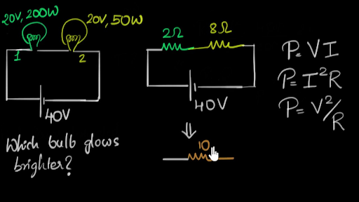
Solved Example Power Dissipated In Bulbs Video Khan Academy

Lm338 Datasheet Adjustable Power Supply 5a And 10a Elec Circuit Power Supply Power Supply Circuit Power

Lm338 Datasheet Adjustable Power Supply 5a And 10a Elec Circuit In 2020 Power Supply Power Supply Circuit Power

How To Save Electricity Current Bill At Home Save Energy Using Capacitor Youtube Capacitors Save Electricity Bill Electricity

Voltage drops across any component in spice are referenced by the node numbers the component lies between so v 1 2 is referencing the voltage between nodes 1 and 2 in the circuit which are the points between which r 1 is located.
A simple electric circuit has 20v battery and resistor of 100 ohm what is the current.

Pin On Electronic

The Post Details A Simple 20 Watt Power Amplifier Circuit Which Uses Only Power Transistors For Th Circuit Diagram Electronic Circuit Projects Circuit Projects

0 30v Variable Power Supply Circuit Diagram At 3a Eleccircuit Com Power Supply Circuit Circuit Diagram Power Supply Design

Simple Adjustable Current Control Circuit Electronic Circuit Projects Constant Current Circuit
Source : pinterest.com
